
Get Started With the Fundamentals of Sound and Acoustics!
By Joe Albano
The latest and greatest gear may get all the attention, but if the acoustics of your studio aren’t suitable, all the toys in the world won’t make for great-sounding recordings. Let’s examine the basics of acoustics, look at issues that can affect our recordings, and discuss practical approaches for optimizing our recording spaces, with an emphasis on control rooms.
Before we jump in, let’s briefly review some underlying physics concepts.
A little background
It’s not exactly news that sound is created by vibrating objects (like a guitar string, drum head, or loudspeaker), and that these vibrations are propagated through the air in waves. Sound waves in the air consist of alternating areas of higher pressure (compression of air molecules) and lower pressure (rarefaction of air molecules), which correspond to the back and forth motion of the vibrating object itself.
Sound waves have three physical properties:
1. The rate at which a sound wave’s vibrations occur. In music this is perceived as the pitch of the sound (for example, A above middle C); in the science of acoustics it is called the frequency, measured in cycles per second, and usually expressed as Hertz (abbr. Hz) as in “The note of A above middle C resonates at the frequency of 440 Hz.”
2. The strength or intensity of the vibrations. In music this is perceived as loudness; in acoustics it is called the wave’s amplitude, measured in decibels (abbr. dB).
3. The pattern of vibration that results in what is called the waveshape or waveform. A sine wave is the simplest of all waveforms, musically it is hardly useful for anything other than to serve as a test signal. The science of acoustics tells us that multiple sine waves sounding together combine to make the complex waveforms of most any sound we hear, musical or otherwise. (Look into the topic of additive synthesis for much more on this.)
The lowest (in frequency or pitch) of those multiple sine waves that make up a complex sound is called the fundamental, and the other, higher sine waves that vibrate faster than the fundamental are called overtones.
Musical sounds (those where we have no trouble defining a musical pitch) are mostly made up of sine waves that vibrate at frequencies that have a simple mathematical relationship, where the overtones are whole-number multiples of the fundamental’s frequency. Example: The fundamental is at 55 Hz and the overtones at 110 Hz, 220 Hz, 440 Hz etc.. These are called harmonic overtones or, simply, harmonics.
Non-musical sounds (noises not definable by musical pitch) are also made up from sine waves, but those sine waves are not vibrating at mathematically related frequencies, at least not according to the simple formula established above. These are called non-harmonic or inharmonic overtones.
As you can imagine, there are many sounds that have lots of both harmonic and non-harmonic overtones—sounds that have sort of a pitch center that is not easily defined with accurate notation: drums, gongs, percussion instruments, also noises like a revving engine or up-and-down, swooshing wind etc. Their waveforms can be extremely complex and interesting to look at on computer screens.
The process by which sounds can be broken down into their component sinewaves is called Fourier Analysis. If you haven’t already done so, check out the process with one of the many computer programs that incorporate this capability, as we’ll be doing when we look at how sound waves behave in a room.
Wavelength of sound waves
For sound waves in the air, the frequency of a particular wave has an associated wavelength—this is the distance the wave travels in the air in the time it takes to complete one full cycle of vibration (one pattern of compression and rarefaction). A sound’s wavelength is related to its frequency, by this formula:
Wavelength (in feet) = 1130 ÷ frequency (in Hertz), where 1130 is the speed of sound in the air (in feet/second).
For example, the wavelength of a low (bass) frequency of 82 Hz (the fundamental frequency of the lowest string on a guitar) is 1130 ÷ 82 = approx. 13.8 feet, while the wavelength of a high note of 4000 Hz (4 kHz, approx. the fundamental of the highest note on a piano) is 1130 ÷ 4000 = 0.28 feet, or a little over 3 inches.
So, at different locations in a room, there will be various compressions and rarefactions corresponding to the positive and negative peaks of the various harmonics of any sound waves moving through that room. When areas of high and low pressure (positive and negative peaks) from different waves or reflections of a wave coincide, they will add and subtract; two high pressure peaks that combine will reinforce for an even greater pressure, while a high pressure and low pressure combination will cancel. This interference is the reason for many of the acoustic issues we’ll be looking at as we delve into room acoustics topics.
Low-frequency anomalies
Okay, with that (exceptionally brief) review out of the way, let’s begin to look at issues that arise in real rooms. We’ll focus mostly on the control room, since acoustic considerations there are usually the most critical, although the issues are equally applicable to live recording spaces.
Low-frequency energy that is unevenly distributed is one of the main problems. When you apply the wavelength formula you’ll see that the wavelengths of bass notes easily exceed the measurements of typical rooms. Example: 55 Hz (the open A string on a bass) works out as follows: 1130 ÷ 55 = 20.54 feet. Few control rooms are deeper than 20’6″. When long waves approach and exceed the dimensions of the room, they are forced to fold back onto themselves, and the resulting cancellations and reinforcements will be localized to specific areas in the room. This results in clearly audible artifacts that must be dealt with.
Fortunately, these interferences can be calculated and mapped out in the room.
Room analysis
In analyzing a room, the first aspect to consider is its overall size, as this will determine the limit of low-frequency support. Frequencies whose wavelengths are longer than half the longest dimension in a room are said to be unsupported in that room.
Take a small room with dimensions of 12’L x 10’W x 8’H. The formula 1130 ÷ 2L (where 1130 = the speed of sound in feet/sec, and 2L = the longest room dimension multiplied by two) gives us the lowest supported frequency in that room: 1130 ÷ 24 = 47.08, about 47 Hz (for reference, the fundamental of the lowest note on a 4-string bass is about 42 Hz).
Frequencies below this will be unsupported, which doesn’t mean that they can’t exist in that room, but that they will be weaker from lack of resonant support (reinforcement by room resonances).
Standing waves
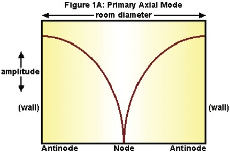 A special problem occurs with the frequency whose wavelength is exactly 1130 ÷ 2L; this will produce what’s called a standing wave or mode. This is a room resonance that occurs when a wave reflects between two parallel surfaces in the room. As the wave is contained by the room, a stationary distribution of reinforcements (boosts in level) and cancellations (null points) will be established as shown in Figure 1A.
The reinforcements (maximum pressure) of the standing wave occur at the walls (the points of reflection), while a cancellation occurs midway between the walls. This happens between every pair of parallel walls in the room (there are three pairs in a rectangular room, front/rear walls, side walls, and floor/ceiling).
Nodes
The locations in the room where the sound wave is canceled are called nodes (in this example the midway point); the areas of maximum reinforcement are called antinodes (in this example at the walls). If you generated a sine wave test tone at that frequency, stood at one wall, and slowly walked to the other wall, you would hear that tone drop in level as you passed the midway point and increase in level again as you approached the opposite wall.
So far we’ve established the first modal frequency in that room, and obviously there are at least three, one for each pair of parallel surfaces. That’s only the beginning—for each room dimension, there are additional modal frequencies.
The second harmonic
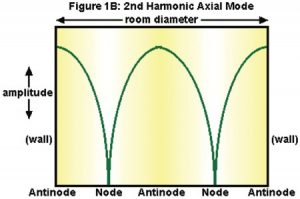 The second harmonic of this first mode will be twice that frequency and therefore half the wavelength—a sound wave of this frequency will also form a standing wave with discrete node and antinode areas. Since the wavelength of the second harmonic is half that of the fundamental’s, the peaks and nulls will be more closely spaced (by half), as illustrated in Figure 1B.
Once again (as always), the standing wave’s reinforcements occur at the walls, but now another reinforcement (Antinode) occurs halfway between, with cancellations (Nodes) a quarter of the way out from each wall. Again, remember this happens for each of the three parallel surfaces in the room.
The plot thickens
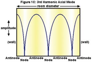 The same effect happens at the third harmonic (3 x the frequency, 1/3 the wavelength) of that initial modal frequency, (Figure 1C), and so on up, with more closely spaced nodes and antinodes. Eventually the wavelengths will become short enough that the reduced strength, greater density, and closer spacing of the various nodes and antinodes will tend to average out rather than be audible at specific spots in the room; this will happen gradually, beginning at around 300–400 Hz.
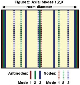
Figure 2 shows a plot of where the nodes and antinodes of the first three of these modes occur in the room. If you plotted each of the three pairs of parallel surfaces and overlaid them, you’d see the specific layout and intersections of the various nodes and antinodes. The particular frequencies affected would of course depend on the room dimensions.
Bass buildup
There will always be a buildup of bass at each wall, and in the corners, where the different modes intersect, generating even more low-frequency energy; the three-way intersection of two walls and ceiling or floor will have the greatest amount of low-end buildup.
Types of modes
And that’s not all—the modes described so far are only one of three types that exist in any rectangular room. These modes, which occur between two parallel surfaces, are called axial modes. They are by far the strongest and most problematic, but they’re not alone. Standing waves also result when sound waves bounce around four surfaces (see Figure 3)—these are called tangential modes; they have half the energy of the axial modes.
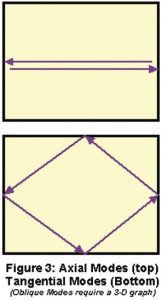 Finally, oblique modes arise from sound waves that bounce around all six surfaces; these have one-quarter the energy of the axial modes.
To fully analyze the low-frequency behavior in a room, all of these modes would have to be calculated and mapped out, but this is difficult to do without test equipment, and since the axial modes are by far the most prominent, we’ll focus on those to create some representative charts of modal behavior in typical rooms.
Mapping out the modes
To determine what specific modal frequencies will be present in a rectangular room, we can use the simple formula given above (1130÷2L) for each room dimension to find the primary axial modes and their first few harmonics, and list them in a chart—we’ll do that for three rooms.
We’ll be looking for two main things: (1) to find and avoid coincidences and near-coincidences (where the same modal frequency develops between two or all three pairs of parallel surfaces), and (2) to achieve relatively even spacing and avoid wide gaps between the frequencies of the modes that are present.
Number one is fairly obvious—if the same modal frequency occurs for, say, both height and width, then the imbalances at that frequency will be twice as bad. This will occur if two (or more) room dimensions are the same, or are multiples of each other (the worst-case scenario would be a cube, L=W=H)—one of the examples will illustrate this.
Number two is based on two assumptions. First, if a lot of closely- and evenly- spaced modes are present in a room, the overall effect will be more of a general reinforcement of the low frequency range. Second, if a few widely-spaced modes are present, musical notes whose fundamentals and harmonics coincide with these modal frequencies will be altered in timbre and noticeably boosted or attenuated in level relative to other notes.
In a bad room, this can be very obvious—imagine a scale played evenly on the bass, with some notes almost dropping out and others booming excessively, depending on the listening position.
There’s no absolute consensus as to what the best distribution of modal frequencies might be. Even spacing is preferable, and it’s been suggested that modal frequency spacing of greater than ~20 Hz will result in audible unevenness, to be avoided or minimized to whatever degree possible.
With this in mind, let’s look at a few simple examples of room mode charts (feel free to analyze your own room this way as well).
 We’ll look at the axial modes for three different rooms, first listing the first four axials under the room dimensions, then listing the first twelve axials for each room in ascending order. We’ll arrange the dimensions from greatest (L) to smallest (H) because this makes it easy to spot the numerical relationships.
As you can see in Figure 4, Room A is not at all ideal: there are wide gaps between modal frequencies, and there are coincidences. Since the 16′ long wall is twice the dimension of the 8′ ceiling, the 2nd (harmonic) mode of the length (70.6 Hz) coincides with the 1st mode between floor and ceiling, also at 70.6 Hz.
Since 8, 12, and 16 are all multiples of 4, at around 141 Hz a three-way coincidence occurs, which will be sure to make the imbalance of any notes/harmonics at that frequency really stand out!
Room B is somewhat better: there are still some uneven, wide spacings, but there is only one coincidence, at around 141 Hz, and it only involves two modes rather than all three.
Room C is even better—the spacings are more even, and there are no exact coincidences.
This last set of room dimensions, 15’5″ L x 12’10” W x 10′ H, was based on one of a group of recommended “Golden Mean” room ratios; these ratios have been analyzed to provide the most even modal distribution (of course, in addition to the Axial modes they also take into account Tangential and Oblique modes).
Golden Ratios for room planning
Here are a few of these Golden Mean room ratios, from various sources. In theory, it doesn’t matter which number applies to which dimension of the actual room, but building practicalities will mean that the shortest is usually the height; since many control rooms are wider than deep, the other two dimensions could interchangeably be width or length, but for consistency’s sake, let’s list the middle dimension as the width and the greatest dimension as the length of the room.
H x W x L
1.00 x 1.14 x 1.39
1.00 x 1.26 x 1.59
1.00 x 1.28 x 1.54
1.00 x 1.30 x 1.90
1.00 x 1.40 x 1.90
1.00 x 1.50 x 2.50
1.00 x 1.60 x 2.33
For a quick idea of how this translates into the real world, assume a room with a 10′ ceiling, and apply the ratios; the formula at the top of the list, for example, yields a room of 10′ x 11’5″ x 13′ 11″ (H x W x L).
What to do?
This naturally brings us to the question of what to do about these modal issues, once the room has been analyzed. In the case of new room or room-in-a-room construction, following the Golden Mean ratios above is an excellent place to start.
If space permits, it’s also recommended that room volume (L x W x H) be at least 1500 cubic feet (for example 16′ x 12′ x 8’=1536 cu’)—this will push the lower-order modes down in frequency and provide greater density and evenness in the useful bass range.
In the case of an existing space, however, adjusting room dimensions is, of course, not usually an option. Sometimes, after mapping out the locations of the nodes and antinodes, simply rearranging the location of speakers and listening position in the room can help to avoid being in the path of the most severe artifacts. Examples: Not establishing a critical listening position right up against a wall; placing speakers in a more neutral location.
But while this can help, even good modal spacing and careful room layout isn’t really an adequate alternative to a truly balanced room response for serious use, so in a professional situation the preferred option is to address problematic standing waves with room treatments.
 Room treatments
One approach, frequently used in studio construction, is the splaying (angling) of the walls/floor/ceiling, to avoid having the parallel surfaces which give rise to standing waves. However, this will not really eliminate standing waves, but will simply shift their distribution in the room slightly. This may help to reduce the severity of some modes a little, but it will also make it more difficult to calculate and map them out.
Unless you have access to computer software to help you map out the room’s response, it’s probably better to stick with a rectangular shape with predictable modal behavior, and turn to other solutions.
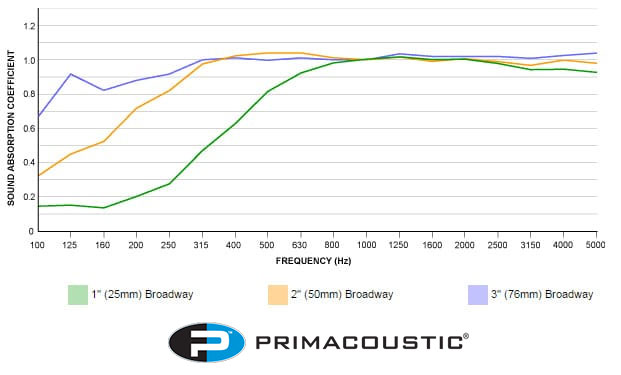
Another way to deal with standing waves might be to absorb them. Unfortunately the absorption of low frequencies (by typical porous absorbers that you could easily apply to walls and surfaces) would require depths that are comparable to the wavelengths of the frequencies to be absorbed, which would be impractical.
In practice, the commonly available sheets and tiles you often see in studios are only effective at mid and higher frequencies, well above those at which standing waves form. To absorb low frequencies, with their room-sized wavelengths, the best approach is to “trap” the low frequency waves via the use of cavities at or behind the walls. This approach has given rise to the term “Bass Traps” for some such cavity-based solutions.
Trapping the bass
A bass trap is a tuned cavity with a depth of a quarter-wavelength of the frequency at which maximum absorption is desired. Such a cavity could be built into one of the parallel walls that are contributing to the formation of a standing wave. The wave would enter the cavity at its point of maximum pressure buildup, at the wall. Inside the cavity, maximum pressure would develop at the back, resulting in zero pressure at the mouth (opening), countering the normal pressure buildup there.
A bass trap will be effective at 1/4 wavelength and odd-numbered multiples of 1/4 wavelength. This technique can be effective, but of course requires some extra depth to be available behind the walls if built in.
Another approach is based on a design called a Helmholz resonator (an example of this is a long-necked bottle). For our purposes this would consist of an opening or series of openings (like the neck of the bottle) into a cavity (or connected series of cavities). The resonant frequency of the cavity is determined by the length of the “neck” and the volume of air in the cavity. Sound is absorbed at and around the resonant frequency (matched to the frequency of a standing wave).
It’s possible to construct your own resonators, usually consisting of a panel with holes or slots in it in front of a cavity (corner placement is a good choice; these can even be free-standing). The exact size and spacing of the holes is the key to “tuning” such a perforated resonator to a particular mode—the formulas involved are not too complex, but there isn’t enough space to really get into the specifics here.
There are quite a few other types of low-frequency absorbers (see the recommended readings at the end of the article), and if building your own is not feasible, many commercial standalone solutions are available that work very well.
Other room concerns
So far we’ve considered the effects of low-frequency waves in the room. There are other issues, related to the propagation of mid and high frequencies. When a mid- or high-frequency sound wave moves through a room, it eventually hits one of the various boundary surfaces (walls, ceiling, floor). When this occurs, the sound wave is either absorbed, transmitted, or reflected.
Absorption means that some or most of the wave’s energy is converted into heat. Transmission means that the wave has some of its energy passed—through the wall, for example. Reflection means that most of the wave’s energy is directed back into the room. This will happen repeatedly as the sound wave hits various surfaces until all its energy is eventually dissipated.
A room where all the surfaces are completely absorptive sounds dead and unnatural, and is unsuitable for music making or listening. Such a room, called an anechoic chamber, would be used for testing purposes, as in the manufacture of loudspeakers for example, to isolate the sound quality of the speaker under test from the room effects.
An overly reflective room is also not ideal—too many reflections tumbling around the room obscure the clarity of music or speech (see below).
An ideal room strikes the right balance between the original sound from the source (i.e. instrument or loudspeaker) and the amount of reflected sound present. Furthermore, it is desirable for the reflected sound to be distributed as evenly as possible throughout the room, providing a comfortable and pleasant sense of ambience (liveness). This even distribution of reflected sound energy is called diffusion, and is generally desirable, as we’ll see. But along the road to this ideal room, there are many pitfalls that we’ll now examine.
Reflections and echoes
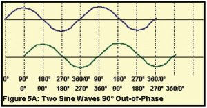 Reflection of sound waves is the behavior we’ll be most concerned with in the next few paragraphs. Just as happens with lower frequencies, when mid- and high-frequency waves reflect back into a room, the positive and negative peaks of the direct (original) sound waves and those of the reflections will cancel and reinforce. This happens because the reflections are delayed in time relative to the direct sound, causing their positive and negative peaks to be offset from those of the
 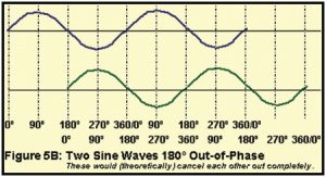 direct sound, which results in the interference (see Figure 5 for an illustration of this).
In describing this, if we express the duration of a single cycle of a wave in measurements of phase, the delayed reflections as shown in Figure 5 can be said to be “out of phase” with the original sound. This phase-induced delay, or phase shift, is inevitable in any normal reflective environment.
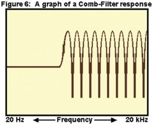
The short wavelengths of mid and high frequencies means that these cancellations and reinforcements occur more frequently all throughout the room rather than being clearly localized to specific broad areas as with standing waves. In a typical room, many complex interferences like this at higher frequencies result in changes in the frequency balance of sound in that room, as illustrated on a frequency response graph in Figure 6. This is called a comb filter response.
While this resulting frequency response may look very ragged, in actuality our hearing systems tend to average out and largely gloss over these subtle, myriad cancellations and reinforcements, and instead may perceive this as a not unpleasant coloration of the sound in a casual listening environment.
However, a recording studio is not a casual listening environment. For example, we depend on what we hear in the control room to make important decisions about the way the sounds in a recording blend and balance. We need to hear exactly what’s in the recording, not a “pleasantly colored” reproduction. Consequently, we need to exert some degree of control over any such effects that impact the neutrality of the monitoring environment.
The hearing process
The first thing to do is to gain an understanding of how our own hearing systems interpret this barrage of direct and reflected sound. When a direct sound reaches our ears followed by a reflection, how we perceive these two sounds is determined by the arrival time of the reflection. If it arrives less than about 50 milliseconds (thousandths of a second) after the original sound does, we perceive only the original direct sound, but the interference effects contributed by the delayed out-of-phase reflection will color the timbre of that sound.
Our auditory system’s perceptual fusing of the direct and reflected sounds, under the conditions described above, is called the precedence effect (or Haas effect)—the ear integrates all reflections within ~50 milliseconds of the first arrival (direct sound). But if a reflection arrives more than ~50 milliseconds later than the direct sound, it is not perceptually fused with the direct sound and is instead heard as a discrete echo.
The actual threshold of the shift in perception from integration to echoes is gradual between about 25–50 milliseconds, and varies depending on the nature of the original sound. For example, for short percussive sounds with sharp attack transients, the perceptual fusing of direct and reflected sounds may break down at only 20 milliseconds of delay, or even less. (A musician calls this “flamming.”)
The delay, or gap, between the direct sound and the first reflection, as well as the spacing of the other (integrated) early reflections determines the acoustic character (our sense of the size and shape) of the room. If there are enough reflective areas, the later reflections, instead of being heard individually as echoes, build up in density and form reverberation, which continues after the direct sound stops, dying away gradually.
Reverberation time (RT60) refers to the time it takes for this reverberant tail to decay by 60 dB. In control rooms this property is usually kept to a minimum by design.
Localization
Another aspect of our hearing in regards to direct and reflected sound is described by the “Law of the First Wavefront.” This says that when we hear a direct sound followed by early reflections, our auditory system not only integrates them, but also determines the localization of this combined sound from the direction of the first arriving sound. So if a sound wave originates from a loudspeaker in front of us and slightly to the left, followed a few milliseconds later by a reflection from the right, we identify everything as coming from the loudspeaker.
However, if the reflected sound is about 10 dB or so louder than the direct sound, the localization towards the direction of the first arrival breaks down, the perceived image shifts, and the direct/reflected sound then appears to be spread out between the actual sources.
Another directional aspect of our auditory perception is that reflections from the same direction as the (direct) source can be 5–10 dB louder before being detected than reflections originating from other directions. This is so because the direct sound masks the reflections coming from the same direction. So strong reflections from the sides of the room (lateral reflections) can be more problematic than those from the front.
In the control room
The presence of early reflections, echoes, and reverberation in a room is normal and adds fullness and a sense of spaciousness to music, but in a control room, too much of this can be a problem. Recordings being monitored already contain recorded ambience, or else they may have artificial ambience added to them, but either way we need to hear the reflections in the recordings more than the ambience of the control room itself. And of course, reflection-based effects like image shifts and colorations of the direct sound also obscure aspects of the recorded sound like panning and tonal balance, so reflected sound must be tightly controlled to insure a good monitoring environment.
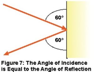 If we’re going to try to control or eliminate certain reflections in a room, we should trace their pathways as they travel through the room. When a sound wave is reflected off a room surface, there is a well-known rule which describes the propagation of that reflected wave: “The angle of incidence is equal to the angle of reflection.” This means that for whatever angle a sound wave strikes a reflective surface, it will bounce off that surface at an equal but opposite angle (see Figure 7). You can see this for yourself by bouncing a flashlight beam off a mirror—and this is actually the basis for a handy means of dealing with these reflections that we’ll discuss below (which we call the “mirror trick”).
The most problematic reflections are the earliest and therefore the strongest. By applying the above rule, reflection pathways can be predicted, and strong reflections can usually be traced from the source (i.e. loudspeaker) to the positions on nearby reflective surfaces where these worst offenders originate.
Damping and diffusion
So, how should we go about addressing these issues? One obvious and successful approach is to deaden reflective surfaces by placing absorptive material on them, eliminating problematic reflections. Since we’re concerned with mid and high frequencies here, with relatively short wavelengths, the familiar foam sheets and panels that we often see in studios are readily available and very effective. These can be hung or affixed to walls and ceiling to dampen reflective surfaces.
As noted earlier, a completely absorptive room would sound unnatural and be unsuitable for any musical application, so the solution is to apply only as much damping as needed to eliminate the most problematic reflections, while allowing enough reflections to remain to give the room an appropriate sense of “liveness.”
LEDE™
Again, the most problematic reflections are the earliest and strongest, coming from reflective surfaces closest to the source. In a control room, if the source is the speakers, this would be the walls and ceiling in the front and front-sides of the room. Reflections from the rear, having traveled a greater distance, would be weaker and, since they arrive much later than the direct sound, will not cause excessive coloration. As a result, they could be allowed to contribute to the necessary ambience in the room. If these rear reflections were further diffused for a more even distribution throughout the room, as described above, that would achieve the best balance while preserving the neutrality at the primary monitoring position (the “sweet spot”).
This approach is often described as LEDE (live-end/dead-end), a term and concept introduced by industry veteran Chip Davis (the trademark is held by Synergetic Audio Concepts, Inc.—www.synaudcon.com). Early applications of this technique completely deadened the front of the room (front wall, side walls, ceiling, except of course the control room window), as far back as the mix position. The back of the room was left live and diffused.
Damping the earliest reflections this way increases the initial time-delay gap, the time between the direct sound and the first of the early reflections which determine the acoustic character of the room. Increasing this gap in the control room allows for early reflections in recordings to be heard more clearly, without the control room imposing its own acoustic signature on everything played in it.
The approach works well, providing a lot of clarity at the monitoring position, but can sometimes result in good but slightly dry-sounding spaces. Some modern approaches tend to use a bit less absorption in the front of the room, damping some reflections and redirecting others away from the sweet spot toward the back of the room, where they can be diffused. If done well, this can provide a somewhat more “live” environment while still maintaining the essential clarity.
The mirror trick
In a low-budget situation you can target the most problematic early reflections and dampen them even without benefit of the computer programs the pros use for this. You’ll improve clarity without excessive cost or analysis. This can be done by using the mirror trick mentioned earlier.
One person sits in the mix position, while another takes a mirror and moves it around a side wall until the person sitting in the sweet spot can see the speaker reflected in the mirror. This shows the path of a sound originating at the speaker, and reflecting from that spot directly to the listening position, based on the “angle of incidence” rule (light reflects just as sound does).
Applying appropriate damping to that spot on the wall will eliminate (or at least reduce) an early, strong, and most likely problematic reflection. You do the same for such reflective locations at both side walls, ceiling, and even the floor. This isolates the most direct and strongest reflections, and damping them can make a noticeable improvement in clarity at the monitoring position, without overly deadening the room.
Flutter echo is another related problem that arises from reflected sound, especially from lateral reflections: A sound wave hits a parallel wall straight on, and (again, in accordance with the “angle of incidence” rule) reflects straight off and over to the other wall, setting up a repetitive back and forth reflection pattern that can result in an audible metallic “ringing.” As with room modes, splaying the walls to avoid parallelism can prevent this, but so will effective damping, as per above, and damping is certainly easier to implement than wall splaying.
The back of the room
 The potential problem in having a live rear end of a control room is that too much reflected energy may be directed straight back at the mix position. To avoid this, various techniques have been used to diffuse, or spread out, this reflected sound. One of the simplest and most traditional is the use of a curved rear wall (see Figure 8A).
This is a convex surface, which (once again, in accordance with the “angle of incidence” rule) redirects reflections, distributing them throughout the room, instead of letting them beam straight back to the listening position. Even a slight curve will have a useful effect here. This curved surface is called a polycylindrical diffusor, and if there is a cavity behind it, it can also help with low frequency absorption.
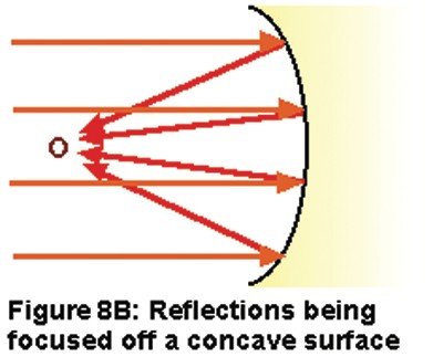
The thing to avoid most is any concave rear surface, which would focus reflected sound at a particular spot in the room (see Figure 8B), exactly the opposite of the desired result (that may be great for parabolic mics, but not for the back of a studio!).
Another approach is to create an irregular surface on the rear walls, to send reflections in many different directions, effectively diffusing the ambient sound field. A wall covering consisting of various sized blocks or grooves can be employed to accomplish this; even a bookcase can be pressed into service in a pinch. However, the best results will be achieved when this kind of surface treatment is not just random, but specifically designed to diffuse sound most effectively at a wide range of frequencies.
More recent computer-assisted designs of this type are able to not only distribute reflections around the room, but also deliver an optimum balance and distribution of all the diffused reflected frequencies. There are many types of these diffusors available. One good example of this approach is a quadratic residue diffusor. This is a panel made up of what appears to be a series of blocks or grooves. They’re not just randomly arranged to simply spread out reflections—their arrangement and depths are determined mathematically by a quadratic residue sequence (there’s a mouthful!), to provide the greatest degree of diffusion and the most even distribution of reflected sound.
Fortunately, for those who tend to cringe at anything more than long division, premade diffusors of this type are available commercially. Though not cheap, they are very effective and recommended if the budget allows.
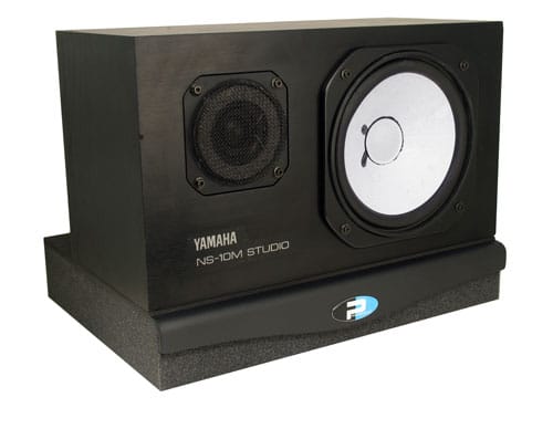
Primacoustic Recoil Stabilizer decouples a loudspeaker from the desk or stand creating tighter bass response and enhances definition.
Additional considerations
Room boundaries are not the only surfaces that can generate reflections. How about that great big console right in front of you? Reflections off the console or work surface and other studio gear like racks can also contribute to a loss of clarity.
Console reflections in particular can be problematic, since they originate right in front of the listening position and therefore can be quite strong. If the speakers are wall- or soffit- mounted, an absorbent “hood” can sometimes be placed behind and over the meter bridge to prevent sound waves from hitting the console surface.
Reflections from console-top monitors are more difficult to eliminate, but at least choosing monitors with narrow, controlled vertical dispersion and angling them carefully will beam less high-frequency sound down to be reflected off the console surface.
Keep other gear out of the direct path of sound from the speakers—use lower racks, or position tall racks to the rear of the mix position. The sharp edges of most racks diffract sound (diffraction is a change in direction of a sound wave caused by an obstacle)—rounding off such sharp edges helps diffuse such reflections. After the room is initially set up and tuned, checking the acoustics as additional pieces of gear are installed can help to identify and prevent new problems from being introduced.
Another approach to minimizing the problematic effects of strong early reflections is to set up the mix position no more than 3 feet or so from the speakers, placing the listener in the speakers’ “near field.” Theoretically, in this zone, the direct sound from the speakers should be predominant over reflections from other surfaces, providing a more neutral response even in a room with less than optimal acoustics.
This approach is called Near-Field Monitoring™, a concept that was trademarked by industry veteran Ed Long. It is usually implemented via the use of console-top monitors. This does work fairly well, the sound in this near-field area is often somewhat smoother than sound from the same speakers in the far-field (at greater listening distances) of the same room.
This type of setup is often recommended for studios where, for one reason or another, room treatments are not able to completely control reflection issues (which includes most small studios). However, near-field monitoring is not a panacea for acoustic problems—standing wave effects will still be present, and as noted above, the possibility of close strong reflections from the console itself can still potentially compromise monitoring accuracy.
What about the live room?
This article has focused on control room acoustics, but the issues in the live (recording) room are the same, though treatments will reflect the different usage of that space. Room modes introduce the same problems, and the same solutions apply. Additionally, being familiar with whatever standing waves may be present in the recording space can help the engineer in determining where to place instruments and microphones (to avoid a mic ending up in a null, for example).
Controlling reflections is also desirable in the live room, but here the criteria may be a bit different. In the recording room we might be more forgiving of colorations and echoes than in the control room. Rather than being a reference environment, the live studio space needs to support the sounds of singers and instruments, and here the acoustics may benefit from some “pleasant coloration” and enhancement of sound, though we certainly want to maintain control.
We may want to have different areas, some more ambient, some more dry (damped), to suit different recording situations, but this need not be implemented as rigorously as in the control room. One common approach to providing varying acoustics in the recording space is to mount two- or three-sided panels with different degrees of absorptive and reflective materials on the different faces. These panels can then be rotated individually to create the desired degree of ambience for a particular session.
In our discussion of control room acoustics we focused on early reflections and ambience, and didn’t really look at reverberation in detail, other than to point out the desirability of a diffuse sound field. In control rooms there’s very little reverb tail by design, so as not to overshadow the ambience and reverberation in recordings. In the live space, however, a good reverberant sound field is an asset, imparting a natural richness and dimension to recordings made there.
Had we focused on live room design, we’d have spent a lot more time discussing how to measure and control various aspects of the reverberant sound field via design criteria and room treatments. Fortunately, there’s no shortage of reference material available on this topic.
The wrap-up
This article has tried to provide an introduction to the complexities of room acoustics, with a few practical suggestions for remedies and treatments. Anyone who plans to really get involved in designing and tuning the acoustics of a recording studio will want to delve much more deeply into the relevant physics and math. An excellent textbook on the subject is the Master Handbook Of Acoustics by F. Alton Everest, which contains both theoretical and practical information in great detail. Two other books that present practical design templates for DIY studio construction are Sound Studio Construction On A Budget, also by Everest, and How To Build A Small Budget Recording Studio From Scratch, by Mike Shea and F. Alton Everest (he does get around, doesn’t he!).
There’s also plenty of information to be found on the Internet that could be of help to any would-be studio designers out there (try the websites of some of the companies that make studio acoustic products, for starters). And to anyone who is designing and building their own recording space, large or small, good luck—it can be daunting, but the results will be worth it!
