
Grounding problems can cause all sorts of audio gremlins—learn how to stop them at the source
By Tom Day
Usually we collect a pile of equipment and over time figure out how to put it all together. The only exception I can think of would be that you’ve just won the lottery and are out to buy everything you’ll ever buy at once.
In reality, people don’t get to plan their studios—we buy bits as we find them and/or find the money. Then we find a space in the rack, a pair of empty jacks on the patchbay, and on we go. As the rig grows, so does the potential for problems, and soon we’ve created an audio disaster area.
This has nothing to do with lots of money or fame. One of the biggest-buck studios I’ve visited had some of the worst laid-out equipment I’ve ever seen. And I’ve stumbled through one-bedroom studios with only three or four pieces of equipment that were nothing but a tangled rat’s nest of cables.
Obviously, there are also pristine environments at all levels. But two overriding factors separate the studios that are easy to work in: good maintenance and planning for expansion. This article is all about what that means.
 Rethinking the room
Even if you’ve been growing your equipment collection in the same room since the ’90s, it won’t hurt to wade your way through a planning exercise. It may even identify a trouble spot in your signal path that’s been bugging you all along. And if your studio is as big a mess as many are after all those years, it usually makes sense to tear it all down and put it together from scratch.
While it probably seems like a waste of time, especially if your system only includes a computer and a few MIDI pieces and a mixer, I recommend drawing a schematic of the equipment connection plan. Before you ever connect a cable or plug in a power cord, draw out the equipment you own and determine the best place in the signal path for each piece. A good example of a planned signal path is the block diagram that you’ll probably find in your mixer’s owner’s manual.
If you aren’t able to do this layout work in a CAD program, consider stealing an old industrial engineering trick. Make a small, rough drawing of each piece of equipment, piece of furniture, and rack cabinet that you’ll have in the room. Cut out the drawings and put them aside for a moment. On scale with your furniture, draw your room, including the lighting and power sources.
Now, using a temporary office adhesive, do a few dozen “what ifs” with the equipment and furniture cutouts on your scale studio facility. Eventually you’ll find the best place for everything and make the best use of your available space.
Transformation
While you’re planning the layout, consider the best physical locations for your equipment. If you can avoid running low-level signal cabling over power transformers, do so. For example, power amps have big, nasty supply transformers than can couple 60 Hz harmonics into just about anything placed nearby.
If you can design your rack and instrument layout to minimize cable lengths, do that too. Electrons like short paths. The shorter your cables, the less likely your wiring will pick up noise and interference from undesirable sources. Short cables also introduce fewer losses in your signal path, due to reactive cabling components (inductance, capacitance, and resistance).
While we’re talking about undesirable noise sources, I should mention a few. Light dimmers, for example, are some of the most insidious things left over from the Evil Empire. There are dimmers specially made to reduce EMI, but they don’t always work as well as advertised. Personally, I think it’s smarter to design your lighting system so that you can illuminate what you need illuminated. Turn off lights when you don’t need them.
Old-style fluorescent lights are almost as evil. The ballasts (transformers) are terrific sources of power line harmonics, and they can plague you when they get near mics, instrument pickups, tape heads, and any other high-gain, low-level signal source. Some mixers seem incapable of shielding their internal circuits from fluorescent fixtures that live anywhere in the vicinity. The compact fluorescent bulbs that screw into normal incandescent bulb sockets are often less of a problem, and I understand low noise shielded fluorescent tube fixtures are also available, but seriously… this is the 21st Century. Go buy LED lights and be done with it!
We mentioned power supply transformers; note that there is an AC-to-DC power supply in nearly every piece of equipment you’ll buy. Some manufacturers save themselves from power supply EMI by using wall warts. These things save money, but they can induce hum into any nearby wires.
 Running interference
Built-in power supplies can be almost anywhere in the cases of equipment, and while their location is usually optimal for that specific piece of gear, the transformer orientation can generate hum and noise in nearby equipment. Most of the time you’re going to stack a half dozen effects and other gear in a rack, piling power supply upon power supply.
With some of the supply transformers at just about every location possible, relative to the other equipment’s’ sensitive circuitry or input connectors, it’s possible that the wrong rack organization can produce a lot of noise at the output of your system.
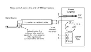
Here’s one simple and fairly reliable method of checking for inter-equipment interference. Start by terminating the input connectors, using a balanced or unbalanced connector shunted (connected) with a 100 to 600 ohm resistor. If you’re testing an XLR, pins 2 & 3 get shunted with the resistor; if it’s an unbalanced connector, shunt hot to cold, signal to ground, or however you like to describe the two terminals.
Then turn off all of the pieces of equipment in the rack but the one you are testing. Crank the gain of the DUT (Device Under Test) to maximum. If you have a DMM (Digital Multi-Meter), connect its leads to an output terminal and measure the output noise. If you don’t have any test equipment, connect the DUT’s output to your board and listen to the noise output of this piece through the board’s headphone output.
Once you have the base noise level, turn on the two surrounding pieces of equipment in the rack. If the noise stays constant, there is no power supply interference. If it increases, turn off each of the surrounding pieces one at a time and see if the interference is caused by one or both. If one of the two is the culprit, try moving it. If it’s both, the DUT may be poorly shielded or you may have a ground loop problem.
With all EMI problems, distance is your friend. If you can afford to give up a rack space between each piece, you’ll most likely have a quieter system than if you have to pack every space in your rack. It’s a good idea to leave a couple of spaces between any piece of equipment that uses a lot of power (like power amplifiers and mixer power supplies) and small signal equipment. You should consider doing this just for the benefits you will get in heat dissipation, if not for the signal-to-noise improvement.
Heat is the enemy of all electrical equipment. Hot air travels upward, so it’s a good idea to plan for this. If you’re going to be driving power amplifiers hard enough that they will get hot (or if you have tube equipment), it’s a good idea to put that kind of equipment at the top of the rack. It’s a better idea to force-ventilate the rack when you’re producing a lot of heat in that enclosed space.
Do not put high temperature equipment under equipment that has moving parts or rubber components, such as tape machines. The heat will accelerate the deterioration of lubrication and flexible items like pinch rollers will quickly harden.
Love connections
Having spent a good portion of my life finding and repairing poor connections, I may be superstitious about wiring and connectors. While I’m not particularly fond of soldering phono (RCA) cables, I still roll my own.
However there are several companies that specialize in audio cabling, and they do a good job at it. You can buy well assembled, high-quality interconnects for not a lot more than what the cable and connectors might cost you.
If you are good with a soldering iron and can do a proper cable prep, do the work yourself. If you aren’t, you’re probably better off buying cables. I think the most significant downside to not being able to make your own cables is that you need to keep plenty of spares on hand for when the inevitable failures occur. The most significant upsides to making your own interconnects are that the cables can be exactly the right length for the job and that you know who to blame for any failures.
Usually, you don’t get many chances to “optimize” once you have your cables and equipment in place. But if you buy professional equipment, you may have an opportunity to use “hard” connections: screw-type barrier strips. If you have a choice between a screwed-down connection and a plug-in connector, always pick the first. Crimp a spade connector (properly sized for the wire used) onto bare cable (do not tin the wire) and tighten the screws.
If you’re really paranoid, which I am, go one extra mile before you haul out the screwdriver. I’ve used Caig Laboratories products since the mid-’70s. Product names like ProGold, DeoxIT, PreservIT, and CaiLube sound pretty New Agey, but the stuff works. I swear by it.
Spray the bare wires and the terminal connectors with DeoxIT before you crimp the two together. Spray the barrier strips before you insert the terminal spade and tighten the screws down. Unless they are plated, spray every tin-lead connector in your system with DeoxIT. If they’re plated, use ProGold. It doesn’t take much and it adds a new application to the “ounce of prevention” adage. I also use those two products on other connectors.
 Ground loop fixes
Now we’ve got stuff in the rack and we’re ready to get connected? Not exactly. We’re not through planning. The evil curse of AC-powered analog electronics is ground loops. Once you have a ground loop problem you can take dozens of troubleshooting hours to find it. A few preventative steps in the beginning will make troubleshooting a lot easier later on.
And you may have noticed that we haven’t actually put a screwdriver to rack screws yet.
Ground loops are probably the most common way in which a studio’s signal-to-noise ratio gets degraded. A ground loop is what happens when there are at least two paths for current that appears on the signal or power ground.
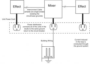
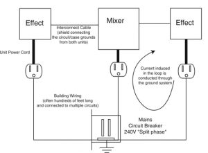
For example, a pair of audio signal processing pieces are connected to two different power outlets. They’re also connected to the same patchbay through their input and output jacks. If there is any potential voltage between the ground connections on those two power outlets, that voltage will find a common path through the signal ground wiring.
Sure enough, that wiring is tied together at the patchbay. The current produced by the ground wiring voltage appears on the shielding of the input and output cables. The electrical components of the cables and the common-mode amplification characteristics of the signal processing equipment will allow the signal on the ground wiring into the equipment’s amplifiers. If the two pieces of equipment are unbalanced, you have no common mode rejection and you may have lots of hum.
[Common-mode rejection (CMR) is the ability of a balanced input amplifier to reject or ignore signals that appear in common (in the same phase and amplitude) on both wires of the input.]
Obviously, one tactic for breaking this closed loop is to cut off the third prong of at least one of the power cords. That’s also a great way to design a system that will provide your spouse with a lump sum payment from your life insurance. Dumb, dumb, dumb. You do not want to set yourself up to be the return path for ground current when a power supply transformer fails and several amps of current are looking for a route back to Mother Earth.
Of course, some equipment is sold with two-prong power wiring. To get away without the safety precaution of a secure case ground path, the external case of the equipment must be “double insulated” from power ground to prevent ground current from finding its way to the case of the product. This is common in consumer hi-fi gear. This equipment can be very difficult to integrate into a recording studio because of grounding issues.
One much better solution to power line ground loops is to use an “isolated ground” for your entire system. This means that you actually take the precaution of making sure there is a real earth ground connected to your equipment racks and other gear. This ground will return all the way back to the main building ground at the circuit panel.
This system is called ‘star grounding.’ To make the job complete, you also make sure that a big, fat solid copper wire runs from the building ground to a copper rod that is driven into the earth (your local codes will determine the length of the rod and gauge of the wire to the panel). A clamp to a cold water tap is nice, but the copper rod is better. The rod ought to be as close to the circuit breaker box as possible. This is very practical for a home studio, and it ought to be one of the first things you do when you start laying out your studio design. This is particularly critical in locations with regular lightning storms.
Once you have this honest-to-NEC (National Electrical Code) ground, you need to run an independent power feed to your studio guaranteeing an independent ground path to your equipment. If all of your audio gear is connected to a single isolated ground circuit, your power ground loops should be minimized. (It’s a great theory, anyway. Connecting the pieces without ground loops can involve magic and luck.)
Balanced circuits are less susceptible to ground loops and other noise sources than unbalanced circuits. But it’s still possible that some ground loop current will find a way into even the best-designed equipment. Some precautions with your interconnecting wiring will help prevent that from happening.
You will need to be prepared to disconnect the occasional ground connection in the signal path to break up loops between the signal ground to the power ground. Ground exists at both ends of the cable, from the case grounds, so completing the shield ground connection is often unnecessary.
I color code my XLR cables (red for single-ended ground, green for connected ground) to make ground loop troubleshooting a little easier. I use about four times as many single-ended ground cables as I do connected versions.
Direct boxes usually have ground-lift switches. If those switches are going to do you any good, you need to wire your XLR connectors so that pin 1 or the XLR case is not connected at one end of your cables. Again, pin 1 is already connected to circuit and case ground at the mixer or effect, so a continuous ground connection is not necessary for shielding.
Unbalanced connections can also benefit from wiring tactics. You can create a simulated balanced connection with a couple of lightweight tricks. If you’re connecting a balanced unit to an unbalanced unit, adding a 50 to 100 ohm resistor to the ground terminal at the unbalanced end of the cable may provide enough resistance to the ground path to divert the ground loop current away from the connection. (See the figure above.)
If the connection is unbalanced to unbalanced, the same 50 to 100 ohm on one of the pin 3 connections may do the same trick. In both cases, use two-conductor shielded cable (like microphone cable) and only terminate the shield wire on one end of the cable.
If you’re careful with the power grounding and the interconnecting shield grounding, you can usually avoid ground loops in your equipment. But the more equipment you have, the more likely it is that you’re going to have problems. If nothing else will make you consider all-in-one multiple-effect boxes, this might. In fact, I think that analog connection hassles ought to make a lot of home studio owners think really hard about going the full digital route.
Chassis and case
Equipment in racks presents other problems. It’s also important for all cases to be grounded properly without creating ground loops, and there are two tactics. The uncommon one is to run a buss bar (very large gauge wire) that’s connected to all the equipment cases.
The other tactic is to isolate the equipment cases, and this is the approach I’ve found to be most useful. If the rack is wood, no problem; if it’s metal, #10 nylon shoulder washers are the answer. Simply put a nylon washer on each side of the rack ear and add a metal flat washer on the outside so the screw doesn’t tear up the nylon insulator—four screws, four flat washers, and eight nylon washers per piece of mounted equipment. This makes the power cord ground the only source of power grounding for each piece of gear, resulting in an effective “star grounding” system.
One other item to watch out for is case-to-case contact. In an effort to pack two inches of circuitry into a one-inch box, some manufacturers chew up every last millimeter of vertical space allowed in the spec, and the case makes contact with the equipment above and/or below it. If you have to, put some kind of insulating shield between units.
Burning in
Okay, we’re all wired up and screwed down. There are just a few other tips I’d offer before you get serious about using your equipment.
Now, the primary failure mode of almost all electronic equipment is “infant mortality.” That means things usually fail during the first 100 hours of use. And the fastest way to get that period behind you is to run your gear continuously for a few days. For most equipment that simply means turning it on and leaving it.
There are two reasons to recommend this. First, the equipment is going to fail when you tell it to rather than at the worst possible time. Second, the failure is going to occur while the equipment is under warranty.
This kind of burn-in used to be done by manufacturers, but, in the interests of reducing manufacturing expenses and process time, now they leave it up to you. So do it. It will only cost you a few watt-hours of power and it might save you a lot of hassle when you can least afford to be hassled.
With electro-mechanical equipment, just running the gear probably isn’t going to provide a decent burn-in. Switches need to be switched. Motors need to spin. Doors need to open, and so on. It won’t hurt your vintage-find tape machine to cycle through a tape or two.
Some equipment’s weak knees will show up just by powering it off and on a few times. Power amplifiers, for example, have large supply surges on power-up. Sometimes all it takes to overstress a poor connection or a weak component is a couple of cycles through the power-on cycle.
Don’t interrupt
This next precaution may complicate the already complicated ground loop planning we’ve done. However, if your power line is not as solid as the power company claims, you may want to protect some parts of your system.
That’s what uninterruptable power supplies (UPS) come in. These devices perform two valuable funtions for critical components in your system: they provide a constant filtered source of AC power, and they give you time to power down your system safely during a blackout.
If you’ve been around computers for any length of time, you know that power brownouts can wreak havoc with computer systems. A fluctuating power supply can cause random memory bit-flips that will contaminate your data or destabilize your system. The UPS’s transformer and filter circuitry prevents that from happening.
A tripped circuit breaker or lightning strike on a nearby power pole transformer will flip every bit that isn’t already at zero. The UPS battery backup and inverter circuitry provide a warning and a reasonable time to save what you’re doing and bail out before the battery goes dead.
The main question when selecting a UPS is what size supply you need, and the spec sheet will help you with that. First decide what needs to be protected and write down the volt-amperage (VA, which is roughly the input wattage rating) requirements for each component. Some equipment specs only tell you the input current requirement; simply multiply the current draw times 120V to get the VA rating. Then add up the VA ratings of the equipment you’ve decided to protect. Compare that total to the chart provided by the UPS manufacturer and decide how much protection you need—and can afford.
For example, you have a computer system that requires 250VA, a computer monitor that uses 125VA, and a hard disk recording system that needs another 250VA. That adds up to 625VA required for the system. Looking at the chart for the 600VA UPS, you see that unit will provide you with about five minutes of backup power, while the 1kVA system will keep you running for ten minutes. Depending on how you work and how long it takes to safely shut your system down (from a real-world situation like having five programs open at once, each with multiple files to save), you can make the most prudent choice for your money.
Happy maintenance
Hopefully some of these words of advice will have hit home, inspired you to rework problem areas, and helped you end up with a much better environment. Good luck.
Special thanks to Michael McKern from Music Tech, Minneapolis, MN (a musicians’ technical school) for his help with this article.
Tom Day has been involved in audio and recording since 1963, with extended stints as a studio manager, audio equipment designer, and manager of QSC’s manufacturing engineering department.